Magnetism · RHR · Ampère's Law · Torque · Solenoid
Right-Hand Rule #1 — B field circles a wire
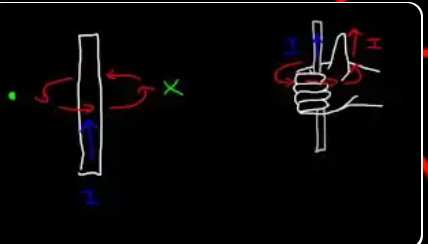
Thumb of right hand points along the current I. Fingers curl in the direction of the magnetic field B around the wire.
"Magnetic fields are created by moving electric charge. ... Whenever there's an electric current that flows through a wire, it creates its own magnetic field. ... It's circular. On the left side, the magnetic field is leaving the page, so it's represented by a dot or a circle. And on the right side, it enters the page, which is symbolized by an X."
"You can use the right hand rule to figure this out. If you take your hand and if you curl it around a pen, with your thumb facing the direction of the current, the way your fingers curl around the pen is the way the magnetic field travels around the wire."
Here's a fact that took physicists 150 years to figure out and still blows students' minds: magnetism is just moving electric charge. There is no separate "magnetic substance" — it's all electricity, dressed up differently because the charges are moving.
A wire with current produces a B field because electrons are streaming through it. A bar magnet produces a B field because electrons are orbiting in fixed patterns inside its atoms (plus quantum "spin" currents). Earth produces a B field because molten iron is circulating in its outer core. Every magnetic field in the universe traces back to moving charges, without exception.
The right-hand rule is about geometry, not physics. It just encodes the fact that the B field wraps around a current in a specific chirality (right-handed, not left-handed). Nature picked one orientation; you match your hand to it. If the universe had been built with the opposite handedness, we'd use a left-hand rule, but the physics would otherwise be identical.
Why the field is "circular" around a wire: by symmetry. A long straight wire looks the same whether you rotate it around its axis or translate it along its length. The magnetic field must respect those symmetries, which forces it to be circular (rotational symmetry) and constant along the wire's length (translational symmetry). These two constraints leave only one possible answer: B forms circles around the wire, with magnitude depending only on the distance r from the wire.
Deep connection to relativity: from the right frame of reference, a magnetic force is actually an electric force "seen from a moving frame." Einstein's 1905 paper on special relativity showed that E and B are really the same field — they just swap around when you change reference frames. Magnetism is a relativistic correction to electricity for moving observers. If the speed of light were infinite, magnetism wouldn't exist.
Getting started with the RHR: find a pen, point it along the current direction, wrap your right hand around it with your thumb along the pen. Your fingers now show which way the B field lines wrap around the wire. Do this physically — actually grip a pen — until it becomes muscle memory. Students who skip the physical practice struggle with RHR for the entire course.
The formula: B = μ₀ I / (2π r)
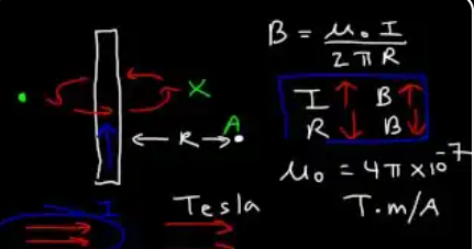
"Now there's an equation that allows you to calculate the strength of the magnetic field created by such a wire, and here's the equation. B is equal to U times I divided by 2 pi R. ... R is the distance between the wire and point A. B is the strength of the magnetic field, and B is measured in units of Tesla or capital T."
"U or mu0 is equal to 4 pi times 10 to the [minus] 7. This is known as the permeability of free space, and the units are Tesla times meters per amp. ... If you increase the magnitude of the current, the strength of the magnetic field generated by this wire will increase as well. ... R is on the bottom, so that means that R is inversely related to B. If you increase the distance between the wire and a point of interest, the magnetic field at that point will be weaker."
"As you move away from the wire, the strength of the magnetic field weakens. ... The number of magnetic lines that you see in a picture is proportional to the strength of the magnetic field. ... If you have more lines that are closer together, the strength of the magnetic field is stronger. So anytime you increase the electric current in a wire the strength of the magnetic field will increase, and as you move away from the wire the strength of the magnetic field will decrease."
This is the most fundamental formula in magnetism. Every piece of it has a meaning you should understand, not just memorize.
- B = magnetic field strength at a point, measured in Tesla (T). One Tesla is a HUGE field — MRI machines use 1-3 T, Earth's field is 50 microtesla (about 20,000× weaker).
- μ₀ = permeability of free space = 4π × 10⁻⁷ T·m/A. This is a universal constant of nature, like c (speed of light) or G (gravitational constant). It's an exact value by definition (since 2019) and represents "how much magnetic field you get per amp in empty space."
- I = current in the wire, in amps. More current → more field, linearly.
- 2π = geometric factor from the circular geometry. The field wraps around the wire in circles, so the "total B times circle length" follows Ampère's Law. The 2π comes from the circumference of a circle (2πr).
- r = perpendicular distance from the wire to the point where you're measuring B, in meters. NOT the distance traveled along the wire.
The 1/r dropoff: doubling your distance from the wire halves the field. Tripling distance thirds it. This is slower than a point-charge's 1/r² electric field but still pretty rapid. At 10 cm, the field is 10× weaker than at 1 cm.
Linear in current: doubling the current doubles the field at any fixed point. Multiply by 10 → field multiplies by 10. This is why high-current applications (MRI coils, electromagnets in junkyards) can create such strong fields — just pump in more amps.
Why μ₀ has 4π built in: the "4π" comes from solid-angle geometry in 3D space. Putting 4π into μ₀ makes the 2π in the denominator of B = μ₀I/(2πr) come out naturally from the geometry of a circle. It's a historical choice that cleans up other formulas.
This formula only works for long straight wires. If you have a short wire or a curved one, you need the Biot-Savart law (more general). But since most problems involve long wires, this formula handles 90% of exam questions.
Example 1 — 45 A wire, find B at 2 cm to the right
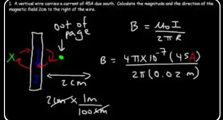
Current points south (down). Using RHR #1, B is out of the page on the right side (and into the page on the left).
"A vertical wire carries a current of 45 amps due south. Calculate the magnitude and the direction of the magnetic field 2 cm to the right of the wire."
"The current is due south, so it's going down. And that means that, using the right hand rule, the magnetic field is going to enter the page on the left side, but on the right side it comes out of the page. ... So we already have the direction of the magnetic field — it's out of the page. ... You should get 4.5 times 10 to the [minus] 4 Tesla."
Every field-from-a-wire problem has two parts: magnitude (use the formula) and direction (use RHR #1). Always solve direction first — it's fast and gives you confidence before you start crunching numbers.
The RHR for this problem: current points south (downward). Grip the wire with your right hand, thumb pointing down. Your fingers curl into the page on the left side of the wire and out of the page on the right side. Since the observer is 2 cm to the right, they see B pointing out of the page.
Cross-product notation (on the diagram):
- ⊙ (dot in circle) = vector pointing OUT of the page (toward you). Think of it as looking at the tip of an arrow flying at you.
- ⊗ (X in circle) = vector pointing INTO the page (away from you). Think of it as looking at the feathers of an arrow flying away.
You'll see these symbols in virtually every 2D magnetism diagram. Memorize them.
Magnitude calculation shortcut: B = μ₀I/(2πr) = (4π×10⁻⁷ × 45)/(2π × 0.02). The π in numerator and denominator cancel: B = (4 × 10⁻⁷ × 45)/(2 × 0.02) = 180×10⁻⁷/0.04 = 4500×10⁻⁷ = 4.5×10⁻⁴ T.
How big is 4.5 × 10⁻⁴ T? About 9× Earth's magnetic field — still tiny in absolute terms, but strong enough that a compass 2 cm from the wire would align with the wire's field and point in the "new" direction, ignoring Earth. This is exactly what Ørsted first noticed in 1820.
Always carry units: meters (for distance), amps (for current), teslas (for field). Mixing cm with meters is the #1 magnitude mistake in all of magnetism.
Example 2 — Solve for r given I and B
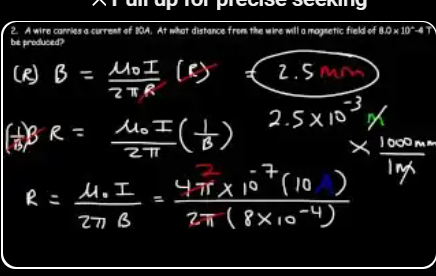
"A wire carries a current of 10 amps. At what distance from the wire will a magnetic field of 8 times 10 to the [minus] 4 Teslas be produced?"
"This is equal to 2.5 times 10 to the [minus] 3, and the units is meters. ... If you multiply by a thousand, this will give you 2.5 millimeters. And so that's the answer."
"By the way, if you ever were to place a compass near a wire, whenever there's an electric current flowing through that wire, it will cause the compass to deflect. You should try it."
The algebra here is just rearranging B = μ₀I/(2πr) to solve for r: multiply both sides by r, divide both by B, and you get r = μ₀I/(2πB). Plug in numbers and you get 2.5 mm.
The 4π / 2π shortcut: notice that μ₀ contains 4π and the formula has 2π in the denominator. The ratio 4π/(2π) = 2, so you can rewrite the formula as r = 2I × 10⁻⁷ / B. Much cleaner: r = 2(10)(10⁻⁷)/(8×10⁻⁴) = 20×10⁻⁷/(8×10⁻⁴) = 2.5×10⁻³ m. Same answer, less typing.
Ørsted's original experiment (1820): the last quote is a reference to Hans Christian Ørsted's famous discovery. He was lecturing about how electric currents produce heat, when he noticed that a compass needle happened to twitch whenever he closed the battery circuit. That single observation — a moving compass next to a current — was the first experimental evidence that electricity and magnetism are connected. Before Ørsted, they were thought to be completely independent phenomena. His discovery kicked off a decade of rapid progress, culminating in Faraday's induction discovery and then Maxwell's equations.
Try it yourself (for real): take any compass, hold it near a wire connected to a battery, and watch the needle swing as you make and break the circuit. The effect is strongest near a coiled wire (solenoid), where the field is concentrated. This was the first experimental verification of Ampère's Law — you can literally recreate it in 30 seconds with a pocket compass and a 9V battery.
Why the result is so small: 2.5 mm is uncomfortably close to a wire. That means an 8×10⁻⁴ T field isn't very strong. Most electronic devices keep their magnetic fields even smaller than Earth's — fields drop off fast (1/r), so staying a few centimeters away gets you down to negligible levels.
F = I L B sin θ — three orientation cases
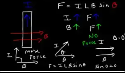
"Now let's say if we have a current carrying wire — what's going to happen if we place this wire inside a magnetic field? Let's say the magnetic field is directed east and the current is moving north."
"A magnetic field exerts no force on a stationary charge. However, if the electric charge is moving, then the magnetic field will exert a force, specifically a magnetic force. ... You can calculate the strength of the magnetic force using this equation: F is equal to I L B sin theta."
"Theta is the angle between the current and the magnetic field. When they are perpendicular, sin 90 is equal to 1, and one basically represents 100%. So the maximum force occurs when the current and the magnetic field are perpendicular to each other."
"When they're parallel, the angle is equal to 0 degrees. Sin 0 is equal to 0. Therefore the magnetic field exerts no magnetic force on a moving charge that moves parallel or even anti-parallel to [the] magnetic field."
F = ILB sin θ is the equation that turns electricity into motion. Every electric motor, every speaker, every magnetic-drive hard disk, every maglev train — they all work because current-carrying wires in magnetic fields feel forces. This single formula underlies trillions of dollars of global industry.
What's going on physically: a current is a stream of charges moving along a wire. Each charge feels F = qv×B. When you sum those individual forces over all the charges in the wire, you get F_total = IL × B (vector form), with magnitude ILB sin θ. The wire "feels" the force as a bulk push because it's bolted together — individual charges push the lattice of the metal.
Stationary charges feel no magnetic force. This is a defining property of B fields — unlike E fields, which push any charge regardless of motion, B only interacts with moving charges. A bar magnet next to a motionless pile of electrons does nothing. The second the electrons move, they suddenly feel a force.
The θ = 0° case: a wire running parallel to a field feels zero force. Think about it: if all the charges are moving along the field direction, there's no "crosswind" for them to experience. The field just slides past without interacting. This is why helical particle motion in a magnetic field has a straight-line component along B (no force) and a circular component perpendicular to B (max force).
The θ = 90° case: maximum force. This is what every motor and speaker is designed for — make the current perpendicular to B so you get the biggest possible mechanical output per amp.
Mnemonic: "I Love Babies" = I, L, B. The sin θ is the only angular modifier. If in doubt, draw the angle between the current direction and the B-field direction, and measure that angle.
RHR #2 (Example A) — I north, B east → F into page
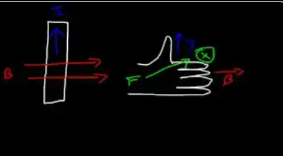
Open-palm right-hand rule: thumb = I, fingers = B, palm pushes outward in the direction of F.
"If the current is due north and [the] magnetic field is directed east, in what direction is the force? Now the force has to be perpendicular to the current and [the] magnetic field."
"You want your thumb to be in a direction of the current, and you want your other four fingers to be in a direction of the magnetic field. ... If you direct it the way it's presented here, it's going to go into the page. The force comes out of the palm of your right hand."
This course uses two different right-hand rules that are easy to mix up. Here's the cheat sheet:
- RHR #1 — B field around a wire: thumb = current direction, curled fingers = B field direction (field circles around the wire).
- RHR #2 — Force on a current in a field: thumb = current, fingers = field, palm push = force.
When to use which: if you're asking "where does the field POINT?" → use RHR #1 (field created by the wire). If you're asking "which way does the wire FEEL a force?" → use RHR #2 (wire in an external field).
Why physics uses two different setups: they answer different questions. RHR #1 connects current → field (Ampère/Biot-Savart). RHR #2 connects current + external field → force (Lorentz law). They're independent pieces of physics.
A common student mistake: trying to use "curl-the-fingers" RHR #1 on force problems, or "thumb-palm" RHR #2 on field problems. If you're wrestling with your hand position and nothing feels right, stop and ask: "Am I looking at the field a current creates, or the force a current feels from an external field?" Choose the rule that matches the question.
Quick check for this slide: current north, field east, force... thumb up, four fingers to the right, palm pushes away from you (into the page). That's correct — force into page.
Test yourself: current up, field into page, force = ? (Answer: east, by RHR #2. Thumb up, fingers into page, palm opens east.)
RHR #2 (Example B) — I east, B into page → F north
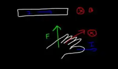
"If we have a wire and the current is directed east and the magnetic field is directed into the page, [in] what direction is the force going to be? ... These three variables have to be perpendicular to each other."
"You want your thumb directed east, that is in the direction of the current, but you want your four fingers to be into the page, and the force comes out of the palm of your right hand. So the force will be directed north."
This example hammers in the same right-hand rule from Slide 6, but with different input directions. Every problem is basically: "thumb = current, fingers = field, palm push = force." The three must be mutually perpendicular, like the edges of a corner of a cube.
The xyz relationship: if current I is along the x-axis and field B is along the y-axis, the force F is along the z-axis. Mathematically, F = IL × B. The "×" is the cross product, which produces a vector perpendicular to both inputs.
Think of it as a corner of a cube: pick any corner of a cube. Three edges meet there, each perpendicular to the other two. The right-hand rule assigns I, B, F to those three edges in a specific order: I (thumb) → B (index) → F (middle). If you curl from I to B, your thumb gives F. This is the "right-hand coordinate system."
For current east + B into page:
- Thumb points east (current)
- Fingers point into the page (field)
- Palm opens northward (force direction)
Alternative method — the FBI rule (not recommended): some teachers use "F, B, I" assignment with different fingers. This introduces confusion with the RHR for charges. Stick with the "palm push" method — one rule for everything.
Check with the xyz test: east = +x. Into page = −z (with out-of-page = +z). So F should be IL×B = x̂ × (−ẑ) = +ŷ, which points north. ✓ The cross-product formalism confirms the palm rule.
Practice advice: do this RHR test on every problem for the first ~20 problems until it becomes muscle memory. After that, you'll see a picture and the force direction will "appear" automatically in your head without conscious effort.
Example 3 — 2.5 m wire, 5 A, B = 2×10⁻³ T at 30°
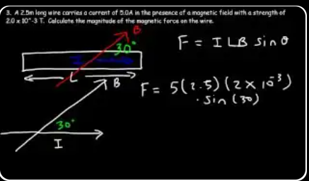
"A 2.5 meter long wire carries a current of 5 amps in the presence of a magnetic field with a strength of 2 times 10 to the [minus] 3 Teslas. Calculate the magnitude of the magnetic force on the wire using the picture shown below."
"Theta is always going to be the angle between the magnetic field and the current. ... 180 minus 30 is 150, and it turns out that sin of 150 and sin of 30 are both equal to 1/2. So whether you choose this angle, which is between I and B, or if you use this angle, the answer will be the same."
"The magnetic force is very small. It's 0.0125 newtons."
The problem shows a wire at 30° to a magnetic field, but there's actually two angles between them: 30° and 150° (the supplement). Which one do you use in F = ILB sin θ?
Answer: it doesn't matter. sin 30° = sin 150° = 0.5. This isn't a coincidence — it's because of a trigonometric identity: sin(180° − θ) = sin θ. The supplementary angle identity guarantees that however you measure the angle between wire and field, you'll get the same force magnitude.
Why the identity exists: the sine function is symmetric around 90°. It rises from 0 at 0° to 1 at 90°, then falls symmetrically back to 0 at 180°. Any pair of angles that are mirror images around 90° (like 30° and 150°) give the same sine value.
Practical upshot: always pick the smaller of the two angles — it's the one that's usually drawn and easier to read. But if you accidentally pick the larger one, your answer is still correct.
Arithmetic detail — "sin 30° = 0.5" is exact: (5)(2.5)(0.002)(0.5) = 0.0125 N. Some common sine values to memorize:
- sin 0° = 0
- sin 30° = 0.5
- sin 45° = √2/2 ≈ 0.707
- sin 60° = √3/2 ≈ 0.866
- sin 90° = 1
You'll see these over and over in physics problems. Having them memorized saves time and reduces calculator dependence.
Why the answer is so small: B = 0.002 T is about 40× Earth's field — unimpressive. Combined with a modest 5 A current and 2.5 m wire, you get 0.0125 N, or about the weight of a paperclip. That's consistent — you don't feel wires in your house jumping around from magnetic forces because Earth's field is tiny.
Example 4 — 35 A west, F/L = 0.75 N/m, B south → find B
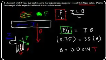
"A current of 35 amps flows due west in a wire that experiences a magnetic force of 0.75 newtons per meter. What is the strength of the magnetic field, which is directed due south?"
"Because the current and the magnetic field are at right angles to each other — because it's 90 degrees, sin 90 is 1 — so we don't need the sign portion of this equation. ... F over L is equal to the current multiplied by the magnetic field. ... It's just going to be 0.75 divided by 35, and so B is equal to 0.0214 Tesla."
"You want to direct your four fingers south and your thumb west, and the force should come out of the page."
Whenever you see "F/L" (force per length) instead of just "F" in a magnetism problem, that's a hint that the length of the wire doesn't matter — you can work directly with the ratio. Rewriting F = ILB sin θ as F/L = IB sin θ removes L entirely and makes everything simpler.
Why this is useful: for infinitely long wires (or very long ones), the total force would be infinite. The force per meter, though, is a perfectly well-defined finite number. Same logic applies to any problem where you don't know (or don't care about) the length.
Units check: F/L is in newtons per meter (N/m), which equals tesla × amp (T·A). Rearranging: B = (F/L)/I → (N/m)/A = N/(A·m) = T. ✓
Backwards-solving for B: this problem is an exam-style twist — instead of giving you B and asking for F, it gives you F/L and asks for B. Algebra: B = (F/L) / I = 0.75 / 35 ≈ 0.0214 T. Notice the answer is small (~21 milliTesla), because a modest force on a strong current doesn't need a huge field.
Direction of the force — even when B is unknown in magnitude: you still use the RHR based on the directions given. Current west + field south → force out of the page. The RHR doesn't care about the magnitudes, only the vectors.
A good exam habit: always check your answer's magnitude for plausibility. 0.021 T is about 40× Earth's field, which is strong but not absurd — it's the kind of field you'd get near a small permanent magnet. If you got B = 21 T or 21 μT, you'd know to recheck your setup.
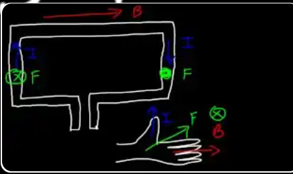
Rectangular loop in a partial B field — net force?
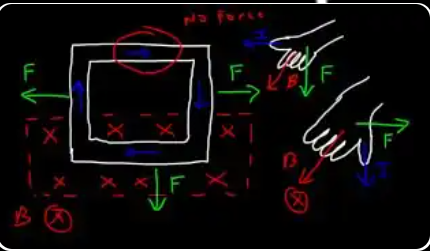
Top side: no field, no force. Left and right sides: forces equal & opposite — cancel. Bottom side: only it's inside the field, so its force is the net force on the loop.
"Let's say [we have] a rectangular metal loop with a current that flows in the metal loop clockwise. ... Only a portion of this loop is inside a magnetic field — that is only the bottom portion. ... Let's say the magnetic field is directed into the page."
"Let's start with this portion of the wire, or of the metal loop. Let's see what the magnetic force on that portion is directed. ... You want to place your thumb facing south. You want the four fingers of your hand to be going into the page. ... The force should come out of your hand — that is, out of the palm of your right hand — and it should be directed east if you do it correctly. So make sure you try that and make sure you can master this right hand rule."
"For the other side, the left side, everything is the same except the current. Because the current is in the opposite direction, the force has to be in the opposite direction. Now these two forces are equal in magnitude, and because they're opposite in direction, they will cancel out."
"In the top part of the loop there's no magnetic field in that region, so therefore there's no force. The net force is going to be based on this portion of the loop, because it's not balanced by [the other portion] of the loop. If the entire loop was in a magnetic field, all the forces would cancel — but since it's not, this one will create a net force."
"Point your thumb towards the left and make sure your four fingers are going into the page. ... You want your thumb directed west and you want your four fingers going into the page. So if you do it correctly, the magnetic force should be coming south, out of the palm of your right hand."
A fully enclosed current loop in a uniform magnetic field experiences ZERO net force. Every segment of the loop has a partner on the opposite side where the current flows the other way, and those forces cancel in pairs. So if the whole loop is inside B, F_net = 0 — guaranteed. (You may still get a torque — see Slides 29-34 — but no linear force.)
What makes partial-field problems interesting: if only part of the loop is inside the field, the cancellation fails. Only the segments inside the field feel a force; the ones outside feel nothing. So whatever force the inside segments produce becomes the net force on the whole loop.
This problem's logic:
- Top side (outside field): no force (no B there)
- Left side and right side (partially inside, both vertical): the parts inside the field experience equal and opposite forces — they cancel.
- Bottom side (fully inside field): horizontal current in B → force = ILB, directed south (by RHR). This is the ONLY unbalanced force, so it's the net force on the loop.
Real-world relevance — motors and pumps: this is exactly how a linear motor or electromagnetic pump works. Put a fluid-carrying pipe in a magnetic field, pass current through the fluid, and the partial-field asymmetry creates a net force that pumps the fluid. Liquid metal cooling systems in nuclear reactors use this trick to move molten sodium without any moving parts.
Also — induction stoves: the partial-coupling of a coil's field with a metal pan creates eddy currents that feel this exact type of force, which in turn generate friction and heat. All from F = IL×B applied to geometry where symmetry doesn't save you.
From F = ILB sinθ to F = Bqv sinθ
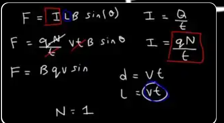
"We talked about how to calculate the magnetic force on a current carrying wire, but what about the magnetic force on a single point charge? ... Capital Q is going to be equal to lowercase q, which is the magnitude of each charged particle, times N, which is the number of charged particles."
"Distance is equal to the speed multiplied by the time, and length can be thought of as distance — they're both measured in meters. ... If you want to find a magnetic force on a single point charge, that means there's only one charge particle, so N is one. ... So this leaves us with f is equal to bqv sin theta."
This derivation bridges two different formulas — one for wires, one for single charges — and shows they're actually the same physics in disguise. A current-carrying wire is just a huge number of moving charges, so a force on a "current" must reduce to a force on individual charges when you look at each one.
The substitutions, step by step:
- Start with F = ILB sin θ (force on a wire of length L carrying current I in field B)
- Current = charge passing per unit time: I = Q/t, where Q is total charge and t is time.
- In time t, the charges move a distance L = vt (where v is their speed).
- Substitute: F = (Q/t)(vt)B sin θ. The t's cancel!
- Simplify: F = QvB sin θ.
- For a single charge, Q = q (one particle). So: F = qvB sin θ.
Why this is beautiful: two independent formulas, derived from completely different physical setups, turn out to be the same equation. Physics is full of these "Aha, they're the same thing" moments — they're what make learning the subject rewarding.
Which formula to use when:
- Problem mentions wires and currents → use F = ILB sin θ
- Problem mentions single charges, protons, electrons, ions → use F = qvB sin θ
- Problem has both → use both; the wire formula is the "sum" of the single-charge formulas over all the charges in the wire
One equation, two faces. The underlying vector form is F = qv×B for a single charge or F = IL×B for a wire segment. These are the same equation, just with different bookkeeping for how many charges are moving.
Charge in B — three orientation cases
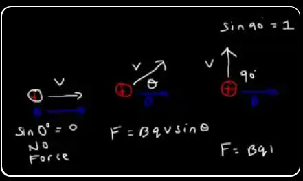
"If we have a proton, and let's say it's moving towards the right, and also the magnetic field is directed towards the right — if these two are parallel, sin 0 is equal to 0, so there's going to be no magnetic force. They have to be perpendicular."
"If the proton is moving at an angle relative to the magnetic field, then you can use the equation f is equal to bqv sin theta. ... If the proton is moving perpendicular to the magnetic field — that is, they're at right angles, or 90 degrees relative to each other — sin 90 is one. So the magnetic force will have its maximum value at this point and is equal to simply bqv."
Every force equation in magnetism has the same sin θ factor: F = ILB sin θ for currents, F = qvB sin θ for charges, τ = NIAB sin θ for torques on loops. It's not a coincidence — it comes from the cross product in the underlying vector equation F = qv×B. A cross product's magnitude is |v||B|sin θ.
The three canonical cases (memorize these):
- θ = 0° (parallel): sin 0 = 0 → NO force. Moving parallel to B is like moving along a field line; nothing happens magnetically.
- θ = 90° (perpendicular): sin 90° = 1 → MAXIMUM force, F = qvB. This is the "clean" case that most textbook problems use.
- Intermediate angle: partial force F = qvB sin θ, with the component parallel to B doing nothing.
Decomposing the velocity: you can also think of it as splitting v into two components: v_∥ (parallel to B) and v_⊥ (perpendicular to B). The parallel component contributes nothing to the force; only v_⊥ = v·sin θ matters. So F = q·v_⊥·B = qvB sin θ. Same answer, different viewpoint.
Why "perpendicular is strongest" makes intuitive sense: think of water running through a paddle wheel. Water flowing parallel to the wheel's axle does nothing — it slides past without pushing anything. Water flowing perpendicular to the axle hits the paddles head-on and transfers maximum momentum. The magnetic force is basically the same — only the "sideways" component of v does work against B.
Helical paths: in the real world, particles rarely move exactly perpendicular to B. The parallel part flies straight forward while the perpendicular part circles around B, producing a helical trajectory — like a corkscrew traveling down a field line. Auroras, Van Allen belts, solar wind in Earth's magnetosphere — all helices.
Proton vs electron — opposite forces in the same B
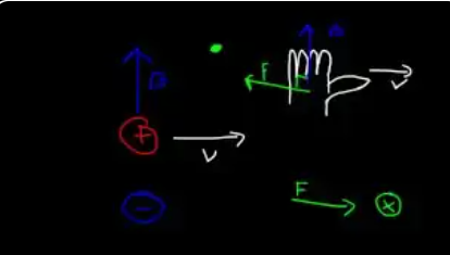
"If we have a proton, and it's moving towards the right, and the magnetic field is directed north, what is the direction of the magnetic force? ... You can use the right hand rule. ... You want your four fingers to be in the direction of magnetic field, and you want your thumb to be in a direction of the velocity. ... The force should come out of the palm of your right hand, [so] it should come out of the page."
"For a proton the magnetic force is out of the page. But for an electron the magnetic force will be in the opposite direction — that is, it's going to be going into the page. So for any negatively charged particle, simply reverse the direction of the magnetic force."
The right-hand rule for a moving charge is: point your fingers along v (velocity), curl them toward B, and your thumb gives the direction of F on a POSITIVE charge. For a negative charge, flip the answer.
Alternative "palm" method (what the transcript uses): thumb along v, fingers along B, palm pushes in the direction of F on a positive charge. Same rule, different finger positions — pick whichever your hand memorizes better.
Why the negative charge flips the answer: the formula F = qv×B has q explicitly multiplying the cross product. If q is negative (like an electron, q = −e), the sign of F is reversed. So you compute the cross product for a positive charge with the RHR, then flip if the charge is negative. Never use the "left hand rule" — it leads to confusion and errors. Just use the right hand and mentally flip the answer for electrons.
Why this matters physically: in a wire, current is conventionally defined as the direction positive charges would flow. But in reality, the moving charges in a copper wire are negative electrons flowing the opposite direction. Both views give the same force on the wire because: (negative charge) × (opposite velocity) = (positive charge) × (original velocity). The two wrongs make a right. This is why F = IL×B works regardless of which charges are actually moving.
Hall effect: if you pass current through a metal strip in a magnetic field, positive and negative charges experience force in opposite perpendicular directions. This sorts charge across the strip, creating a tiny voltage difference — the Hall voltage. By measuring the sign of the Hall voltage, you can determine whether the charge carriers in a material are electrons (most metals) or holes (some semiconductors). This is how we actually know electrons are the current carriers in most materials.
Example 5 — Proton east in B into page
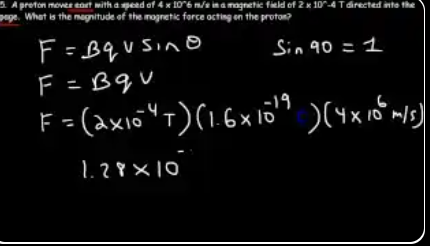
"A proton moves east with a speed of 4 times 10 to the 6 m/s in a magnetic field of 2 times 10 to the [minus] 4 Teslas, directed into the page. What is the magnitude of the magnetic force acting on [the] proton?"
"Because the velocity and the magnetic field are perpendicular ... the angle has to be 90 degrees, and sin 90 is 1, so f is simply equal to bqv. ... Q is the charge of just one proton — the charge of a proton is 1.6 times 10 to the [negative] 19 coulombs. ... You should get 1.28 times 10 to the [minus] 16 newtons."
1.28 × 10⁻¹⁶ N sounds laughably small — and it is, on human scales. For perspective, the force of gravity on a single grain of sand is about 10⁻⁶ N, which is already a billion times larger than this force. So why does it matter?
Because the proton is REALLY tiny. With a mass of 1.67 × 10⁻²⁷ kg, the acceleration that tiny force produces is:
a = F/m = 1.28 × 10⁻¹⁶ / 1.67 × 10⁻²⁷ ≈ 7.7 × 10¹⁰ m/s²
That's 77 billion m/s² — about 8 billion g's. A human would be vaporized instantly. But the proton, being so tiny, barely notices. Newton's 2nd law doesn't care about absolute size, only the ratio F/m.
The force is perfectly perpendicular — it never speeds the proton up. Even with this gigantic acceleration, the proton's speed stays at 4 × 10⁶ m/s forever. Only its direction changes. The acceleration is purely centripetal — pointing inward toward the center of the orbit.
Orbit radius from this force: using R = mv/(qB) = (1.67×10⁻²⁷)(4×10⁶) / (1.6×10⁻¹⁹ × 2×10⁻⁴) = 208 m. Yep — a 200-meter orbit. Weak fields make BIG circles. Strong fields like 2 T (Slide 18) give centimeter-scale orbits at the same speed.
Take-home: the absolute magnitude of F is meaningless without context. Always compare to the particle's mass to find the acceleration, or to its momentum to find the orbit size. Tiny forces on tiny particles produce huge effects.
The magnetic force is centripetal — circular motion
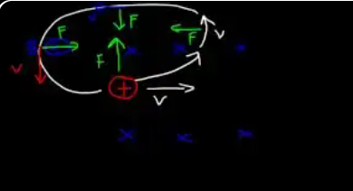
"If we have a proton and it's moving towards the right and the magnetic field is directed everywhere into the page ... where is the magnetic force? If you direct your thumb towards the right and your four fingers into the page, the magnetic force will be directed north."
"Whenever force and velocity are perpendicular to each other, the object will turn. ... Eventually, the particle is going to be moving in a direction of the force. ... For a moving charge particle, the magnetic force behaves as a centripetal force, or a center-seeking force."
This is one of the coolest and most surprising facts in physics: the magnetic force does ZERO work on a moving charge, ever. It can change the direction of velocity, but it can never speed the particle up or slow it down.
Why? Work is W = F·d·cos(angle between F and d). The magnetic force F is always perpendicular to the velocity v (because F = qv×B, and a cross-product is always perpendicular to both inputs). Displacement d is in the direction of v. So the angle between F and d is always 90°, and cos 90° = 0. No work, ever.
What does it do then? The magnetic force only changes direction, never magnitude. The particle's kinetic energy ½mv² stays constant, but v's direction rotates. That's exactly what happens in circular motion: the speed stays the same, only direction changes. Magnetic forces are nature's perfect steering — they bend paths without accelerating them.
The circle emerges automatically: if force is always perpendicular to velocity and constant in magnitude, the particle traces a circle. Think about it: the force is always pointing toward some center (the center of the circle), and the particle's trajectory rotates around that center forever (or until it hits something). This is the definition of circular motion.
Hybrid motion — helices: if the particle's velocity isn't fully perpendicular to B (say it has some component parallel to B), then only the perpendicular component circles, while the parallel component moves in a straight line along the field. The combined path is a helix — a spiral along the field lines. This is how charged particles travel through Earth's magnetic field, spiraling from one pole to the other along field lines.
Proton circles CCW, electron circles CW (same B)
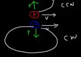
"What if we have an electron? If we had an electron, the situation will be opposite. As the electron is moving in the same direction as the proton, it's going to feel a force in the opposite direction. ... The proton felt a force that was directed north; the electron will feel a force directed in the opposite direction, that is south."
"As the proton moves in the counterclockwise direction, the electron will move in a clockwise direction. So they will move in an opposite direction."
Protons and electrons in the same field circle in opposite directions. This is a direct consequence of F = qv×B: flipping the sign of q flips the direction of F, which flips the direction of circulation.
Memory trick: in a B field pointing into the page, positive charges circle counterclockwise and negative charges circle clockwise. Reverse the field direction and both reverse.
Why this matters in real devices:
- Mass spectrometers: separate ions by mass because R = mv/(qB). Heavier ions arc wider, lighter ones arc tighter, even with the same charge. Different elements end up at different detector positions.
- Cyclotrons: accelerate both positive and negative particles, but the circulation direction differs, so the accelerating gap must switch polarity accordingly.
- Magnetic bottle / mirror: traps charged particles (both signs) by making B stronger at the ends. Used in fusion research.
- Cosmic rays in Earth's field: positively charged protons and negatively charged electrons spiral in opposite directions along Earth's field lines, which is why auroras produce the color patterns they do.
Inside a cloud chamber: particle physics detectors used to reveal tracks of charged particles — looking at how the track curves in a known B field lets you immediately tell charge sign and momentum. This is how the positron (the antimatter electron) was discovered in 1932: a curve going "the wrong way" for an electron but with the electron's mass.
Same speed → same period (almost): protons and electrons in the same B circle with different radii (R ∝ m), but the orbital period T = 2πm/(qB) is also proportional to m. The lighter electron orbits smaller and faster than the heavier proton by a factor of ~1836.
Radius of curvature — set Fc = Fb
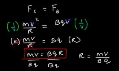
"How can we calculate the radius of curvature that a proton or electron might travel in a circle? ... If you ever get a question like this, what you need to do is set the centripetal force equal to the magnetic force."
"The centripetal force is equal to mv squared divided by R, which is the radius of the circle. The magnetic force is equal to bqv. ... Make sure you write down this equation: MV is equal to BQR — because in this format, you can solve for anything."
When a physics problem asks for the radius of a circular motion, the standard move is to set two expressions for force equal to each other: the force causing the circular motion on one side, and the required centripetal force on the other.
What is centripetal force? It's not a new kind of force — it's the requirement for any circular motion. Any object moving in a circle of radius R at speed v needs an inward-pointing force of magnitude mv²/R. This force can come from gravity (planets), tension (ball on a string), friction (car turning on a road), or — in this case — the magnetic force on a moving charge.
The setup: in magnetism, the "real" force is F_magnetic = qvB. The circular-motion requirement is F_centripetal = mv²/R. Set them equal: qvB = mv²/R. Cancel one v from each side: qB = mv/R. Solve for R: R = mv/(qB).
Why the v cancels: look carefully — magnetic force has one v, centripetal force has v². After cancellation, the R depends linearly on v (not quadratically). This is why faster particles don't loop in smaller circles (as intuition might suggest) — instead they loop in bigger ones, because their momentum fights the turning force harder.
"mv = BqR" as the master equation: the professor is right — write it in this form and you can rearrange to solve for any unknown: R = mv/(Bq), v = BqR/m, m = BqR/v, q = mv/(BR), or B = mv/(qR). All of these show up in different problems.
Period of orbit (bonus result): T = 2πR/v = 2πm/(qB). Notice that the period doesn't depend on speed or radius — all particles of the same charge and mass orbit with the same frequency regardless of how fast they're going! This is called the cyclotron frequency and is the key to why cyclotrons work.
Example 6a — proton radius in 2.5 T field
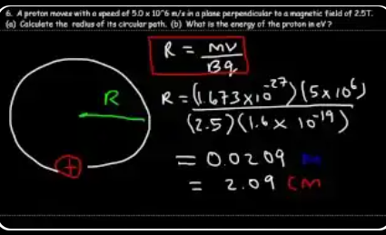
"A proton moves with a speed of 5 times 10 to the 6 m/s in a plane perpendicular to a magnetic field of 2.5 Tesla. Calculate the radius of its circular path."
"The mass of a proton is about 1.673 times 10 to the [minus] 27 kilograms. ... The charge of a proton — which is the same as that of an electron but the opposite sign — is 1.6 times 10 to the [negative] 19 coulombs. ... You should get 0.0209 meters, which is equal to 2.09 cm."
For magnetism problems, you'll need to recognize a handful of fundamental constants on sight:
- Proton mass: m_p = 1.673 × 10⁻²⁷ kg
- Electron mass: m_e = 9.109 × 10⁻³¹ kg (about 1836× lighter than a proton)
- Elementary charge: e = 1.602 × 10⁻¹⁹ C (proton positive, electron negative)
- Speed of light: c = 3 × 10⁸ m/s
- μ₀ (permeability of free space): 4π × 10⁻⁷ T·m/A ≈ 1.257 × 10⁻⁶
- ε₀ (permittivity of free space): 8.854 × 10⁻¹² C²/(N·m²)
- Coulomb's k: 1/(4πε₀) ≈ 9 × 10⁹ N·m²/C²
Dimensional analysis check for R = mv/(qB): [mv] = kg·m/s (momentum). [qB] = C·T = C·(kg/(A·s²)) = A·s·kg/(A·s²) = kg/s. So mv/qB has units (kg·m/s)/(kg/s) = m. Meters. ✓
Physical interpretation of R = mv/qB:
- Higher mass m → bigger radius (heavy particles are harder to turn)
- Higher velocity v → bigger radius (fast particles resist bending more)
- Higher charge q → smaller radius (bigger force = tighter turn)
- Higher field B → smaller radius (stronger push = tighter turn)
Comparison: for the same 5 × 10⁶ m/s speed and 2.5 T field, an electron (1836× lighter) would have R_e = R_p / 1836 ≈ 11 micrometers. This is why electrons are used in small instruments (CRT screens, mass spectrometers) while protons need bigger ones (cyclotrons).
Real device check: a 2 cm radius orbit at 5 × 10⁶ m/s means the proton orbits in about 2π(0.02)/(5×10⁶) ≈ 25 nanoseconds — or 40 million revolutions per second. Cyclotrons exploit this exact periodic motion to accelerate particles at a precise frequency.
Example 6b — kinetic energy in electron-volts
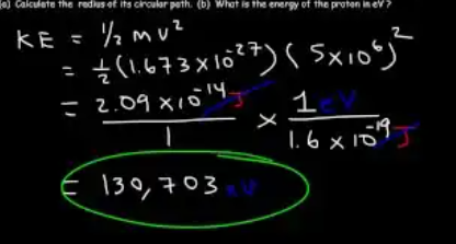
"What is the energy of the proton in electron volts? ... A moving object has kinetic energy. Any object in motion contains kinetic energy, [which] is 1/2 mv squared."
"This is equal to 2.09 times 10 to the [minus] 14 joules. Now once you have the energy in joules, you can convert it to electron volts. ... One electron volt is equal to 1.6 times 10 to the [minus] 19 joules. ... [Which gives 130,703] electron volts."
A proton at 5 × 10⁶ m/s is fast — about 1.7% of the speed of light. At this speed, relativistic corrections are still small (a few thousandths of a percent), so the classical formula KE = ½mv² still gives a good answer. Above about 10% c, you need the relativistic formula KE = (γ − 1)mc² instead.
Why this speed matters: 130 keV is characteristic of particles in sun-like stellar cores (which run at millions of kelvin) and in medical imaging machines. The protons in proton-beam cancer therapy start at around 250 MeV — nearly 2000× more energetic than this example. The LHC protons reach 7 TeV — 50 million times more.
The order-of-magnitude math: (1.67 × 10⁻²⁷)(5 × 10⁶)² = (1.67 × 10⁻²⁷)(2.5 × 10¹³) = 4.18 × 10⁻¹⁴. Half of that is 2.09 × 10⁻¹⁴ J. Doing this in scientific notation keeps the exponent tracking straightforward — multiply the mantissas, add the exponents.
Why convert to eV: 2.09 × 10⁻¹⁴ J is an abstract number with too many zeros. 130,703 eV is immediately recognizable: "about 130 keV, the range of a soft X-ray or an accelerated electron in an old CRT TV." Physicists use eV precisely because it gives human-scale numbers for sub-atomic processes.
The conversion trick: divide joules by 1.6 × 10⁻¹⁹ to get eV. That's just canceling one unit for another — a pure dimensional conversion like converting meters to feet.
Why 1 eV = 1.6 × 10⁻¹⁹ J
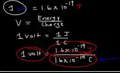
"Electric potential — which is measured in volts — is equal to the electric potential energy, which is measured in joules, divided by the charge. So the unit volt — one volt — is equal to one joule per one coulomb."
"An electron has a charge of 1.6 times 10 to the [negative] 19 coulombs. ... An electron with one volt will have an energy of 1.6 times 10 to the [negative] 19 joules. ... Voltage is really work per unit charge. Electric potential is energy per unit charge."
The electron-volt (eV) is a unit of energy, not voltage. It's defined as "the energy gained by one electron moving through a potential difference of 1 volt." Because an electron's charge is e = 1.6 × 10⁻¹⁹ C, the energy is simply (charge)(voltage) = (1.6 × 10⁻¹⁹ C)(1 V) = 1.6 × 10⁻¹⁹ J.
Why physicists prefer eV over joules for small things: one joule is enormous compared to the energies of individual particles. An electron's rest-mass energy is about 511,000 eV ≈ 8 × 10⁻¹⁴ J — that's a 14-digit tiny number in joules but just "511 keV" in electron-volts. Particle physics uses:
- eV — atomic and molecular binding energies (hydrogen: 13.6 eV)
- keV — X-rays (10–100 keV)
- MeV — nuclear physics, particle rest masses (proton: 938 MeV)
- GeV — high-energy physics (LHC beams: 7000 GeV = 7 TeV)
- TeV — collider energies
The formula connection: kinetic energy of a charged particle accelerated through voltage V is KE = qV. If q = 1 e and V = 1 volt, then KE = 1 eV by definition. An electron accelerated by a 100,000 V potential gains 100,000 eV = 100 keV of kinetic energy. This is exactly how CRT TVs and old X-ray tubes worked.
Converting eV to J: just multiply by e = 1.6 × 10⁻¹⁹. Converting J to eV: divide by 1.6 × 10⁻¹⁹. This is why the previous slide's 2.09 × 10⁻¹⁴ J ÷ (1.6 × 10⁻¹⁹) = 130,703 eV.
Fun fact: mosquitoes flying at top speed have roughly 10¹² eV of kinetic energy — about the same as a single proton in the LHC. Scale matters!
Two parallel wires — same direction attract, opposite repel
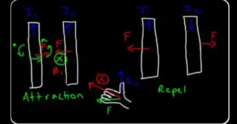
"If we have two wires parallel to each other ... and these two currents are in the same direction, will these two wires attract each other or will they repel? It turns out that these two wires will attract each other if they have a current in the same direction. Now if there's two wires with the opposite current ... they will repel each other."
"Wire one creates a magnetic field because it has a moving charge — it has a current. And that magnetic field exerts a force on wire two. ... Wire two sees a magnetic field that's going into the page. ... The force is going to come out of the palm of your hand, and it turns out that force is directed towards wire one — so it's a force of attraction."
This is one of the most counterintuitive results in electromagnetism: two wires carrying current in the same direction attract each other, while two wires carrying current in opposite directions repel. If you first learn about Coulomb's Law (like charges repel, opposites attract), this feels completely backwards.
The RHR walk-through: say both wires carry current "up" (north). Wire 1 creates a magnetic field that, at wire 2's location, points into the page (use RHR #1). Now wire 2 has current up in a field pointing into the page. Applying RHR #2 to wire 2: thumb up, fingers into page, palm pushes toward wire 1. So wire 2 is pushed toward wire 1 — attraction.
The mirror reasoning for repulsion: if wire 2 carries current in the opposite direction (down), everything else stays the same but the force reverses. Now wire 2 is pushed away from wire 1 — repulsion.
"Like charges repel, but like currents attract" is a deep result. The electric rule comes from Coulomb's law acting on static charges. The magnetic rule comes from the fact that the magnetic field encircles wires and the force is a cross-product (I × B), not a simple attraction to field lines. These are two genuinely different rules.
How to remember it: think of power cables in your house. The "hot" wire and the "neutral" wire carry currents in opposite directions (the current goes out on one and returns on the other). They repel slightly, which is why loose cables sometimes rattle. If they carried current in the same direction, they'd clamp together. This is also why DC transmission lines bundle their pair with physical separators.
Historic note: Ampère himself first demonstrated this in 1820, shortly after Oersted discovered that electric currents deflect compasses. It was part of the observation that united electricity and magnetism into one phenomenon — electromagnetism.
Deriving the force between two parallel wires
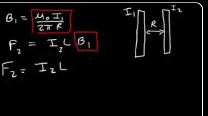
"Wire one creates a magnetic field B1, which is U times I1 over 2 pi R, where R is the distance between the two wires."
"The force on wire 2, which we'll call F2, is equal to the current on that wire times the length times the magnetic field created by wire 1. So what we're going to do now is replace B1 with mu0 I1 over 2 pi R. ... F2 and F1, they have the same magnitude."
This derivation is really "two ideas bolted together." Wire 1 produces a magnetic field (Slide 2's formula). Wire 2 sits in that field carrying a current, and any current in a field feels F = ILB (Slide 5's formula). Combine them and you get F = μ₀I₁I₂L/(2πR).
The two-step mental picture:
- Step 1 — wire 1's field at wire 2's location: B₁ = μ₀I₁/(2πR), where R is the distance between wires.
- Step 2 — force on wire 2 in that field: F₂ = I₂·L·B₁ = I₂·L·μ₀I₁/(2πR).
Newton's third law in action: by symmetry, you could also calculate B₂ at wire 1's location and then F₁ on wire 1. You'd get the exact same magnitude. The two wires push (or pull) each other with equal and opposite forces — which is exactly what Newton's third law requires. The physics is automatically self-consistent.
The force per unit length: dividing both sides by L gives F/L = μ₀I₁I₂/(2πR). This is the more common form you'll see in textbooks because it doesn't depend on how long the wires are — it's a property of the current pair and their separation. Infinite wires are an idealization; force per meter is what physically matters.
Why the formula contains both currents multiplied: it makes sense — if either wire is carrying zero current, there's no field and no force. Doubling either current doubles the force; doubling both gives 4× the force. Current-current interactions are quadratic in scale.
Example 7 — 30 m wires, 2 cm apart, 50 A same direction
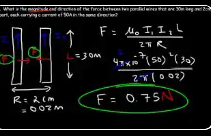
"What is the magnitude and direction of the force between two parallel wires that are 30 meters long and 2 cm apart, each carrying a current of 50 amps in the same direction?"
"For these type of problems, there's only two answers for the direction — either the force is attractive, or they will repel. Because the currents are in the same direction, we have a force of attraction. ... So the force between these two wires is 0.75 newtons."
Every parallel-wire problem reduces to plugging numbers into F = μ₀I₁I₂L/(2πR). Five inputs: the two currents, the length of the wires, the distance between them, and the constant μ₀. Then do arithmetic.
The canceling trick: notice that 4π in the numerator of μ₀ and 2π in the denominator leave you with 2 × 10⁻⁷. So you can rewrite the formula as F = (2×10⁻⁷)·I₁I₂·L/R. This shaves one step off the arithmetic and makes order-of-magnitude estimates faster.
Crunching this example: F = (2×10⁻⁷)(50)(50)(30)/(0.02) = (2×10⁻⁷)(2500)(30)/(0.02) = (2×10⁻⁷)(75,000/0.02) = (2×10⁻⁷)(3,750,000) = 0.75 N. ✓
Always convert cm to m first: 2 cm → 0.02 m. If you leave it as 2, you'll be off by a factor of 100. Distance and length must be in meters for μ₀ to give forces in newtons.
I²L/R scaling: the force is quadratic in current (I²), linear in wire length, and inversely proportional to separation. That means:
- Double both currents → force quadruples (I² scaling)
- Double the wire length → force doubles
- Halve the separation → force doubles
This is why coil windings in electromagnets generate such large forces: short separations × high current² gives enormous force per unit length. It's also why closely-packed power cables need robust mechanical clamps.
Example 7 — final answer summary
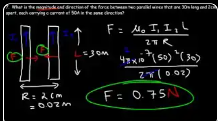
Same problem as the previous slide — restated cleanly as a final-answer card. F = 0.75 N, attraction.
"The force between these two wires is 0.75 newtons, and [the] direction is a force of attraction. These two forces will be pointed towards each other."
0.75 newtons sounds small, but spread across 30 meters of wire, that's only 0.025 N/m (2.5 grams per meter of wire length). For two wires carrying 50 A just 2 cm apart, that's surprisingly modest — but enough to cause real engineering problems at scale.
Why the ampere was defined this way: before 2019, the official definition of the ampere was: "that constant current which, if maintained in two straight parallel conductors of infinite length, of negligible circular cross-section, placed 1 meter apart in vacuum, would produce between these conductors a force equal to 2 × 10⁻⁷ N per meter of length." Read that definition carefully — it's literally this problem. The ampere was defined as the current that produces a specific force between parallel wires.
In 2019 the definition changed: the SI now defines the ampere in terms of the elementary charge e = 1.602176634 × 10⁻¹⁹ C exactly, with no reference to wires. But the old wire-force definition is still a useful mental picture and a great way to see why μ₀ has its strange value of 4π × 10⁻⁷.
At industrial scales the forces are no joke: a power line might carry 1000 A, with wires 50 cm apart. The force per meter becomes F/L = μ₀I²/(2πR) = (4π×10⁻⁷)(10⁶)/(2π·0.5) = 0.4 N/m. In strong short-circuit events, currents of 100,000 A for a fraction of a second can rip power bus bars apart with explosive force. This is why substations use massive steel supports for their conductors.
MRI machines and fusion reactors — places with extremely high currents and strong B fields — must account for mechanical stress on coils from the I×B force. In tokamaks, the superconducting coils experience Lorentz forces equivalent to thousands of tons per square meter.
Ampère's Law — recovering B = μ₀I/(2πR)
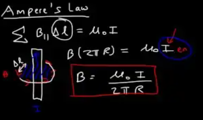
"Ampere's law describes the relationship between the current and magnetic field produced by that current. ... The sum of all the magnetic fields that is parallel to any segments that the magnetic field passes through, that's going to be equal to mu0 times the current enclosed by the path that the magnetic field makes — and it has to be a closed path."
"The path that the magnetic field travels is basically the path of a circle, so delta L is really 2 pi R. ... So it's going to be B times 2 pi R, which equals mu0 times I. ... The current in this equation is the current that is enclosed by this loop."
Ampère's Law says: take any closed loop in space, add up the magnetic field along that loop, and the result equals μ₀ times the current passing through the loop. Written mathematically: ∮ B·dl = μ₀·I_enclosed.
The analogy to Gauss's Law: for electricity, Gauss's Law says "total flux through a surface = enclosed charge divided by ε₀." For magnetism, Ampère's Law says "total B along a loop = enclosed current times μ₀." Both are about "how much field gets generated by some source."
Why it recovers B = μ₀I/(2πR): pick a circle of radius R around a long wire as your Amperian loop. By symmetry, B has the same magnitude at every point on the circle and is tangent to it. So ∮ B·dl = B·(circumference) = B·(2πR). The current enclosed is just I. Set them equal: B·(2πR) = μ₀I → B = μ₀I/(2πR). That's the formula from Slide 2!
Why Ampère's Law is more powerful than the formula: the formula B = μ₀I/(2πR) only works for a single long straight wire. Ampère's Law works for any current distribution: solenoids, toroids, current sheets, cables with a core. It's the master equation; the wire formula is just one application.
The "symmetry trick": Ampère's Law is only useful when the current distribution has high symmetry (cylindrical, planar, toroidal). Then you can argue that B is constant along certain paths, pull it out of the integral, and solve. For weird asymmetric current shapes, you'd need the Biot-Savart Law instead — which is painful and usually done with a computer.
It's also Maxwell's third equation (in the differential form, it becomes ∇×B = μ₀J). When Maxwell later added a "displacement current" correction, Ampère's Law became the equation responsible for electromagnetic waves — the same math that gives us light, radio, and WiFi.
Solenoid — Ampère's Law on the rectangular path
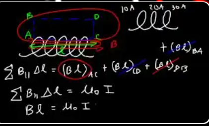
Of the four segments of the rectangular Ampère loop, only AC (inside, parallel to B) contributes — that's why we get B · L = μ₀ Ienc.
"A solenoid is basically a device with many loops of wire. ... For every loop that you add, you increase the strength of the magnetic field inside the wire. And so solenoids are very useful for creating powerful magnetic fields."
"Segment BD is outside of the solenoid, and the magnetic field is very weak outside of the solenoid, so we can say that the contribution ... is very small — so it's negligible. ... BA and DC, they're perpendicular to the magnetic field that is inside the solenoid ... so we can eliminate BA and DC. ... Segment AC is the most important segment because ... it's parallel to the magnetic field that is inside the solenoid, and that magnetic field is the strongest one."
Ampère's Law works for any closed path, but the whole trick is picking a path where the math is simple. For a solenoid, the clever choice is a rectangular path that has one side running inside the solenoid (parallel to B) and the opposite side running outside (where B ≈ 0).
Why this rectangle makes everything cancel:
- Inside segment (AC): B is strong and parallel to the path → contribution = B·L (nonzero)
- Outside segment (BD): B is nearly zero → contribution ≈ 0
- Top & bottom segments (BA and DC): B is perpendicular to the path (B points along the axis, path goes sideways) → contribution = 0 (because cos 90° = 0)
So only one segment contributes: ∮ B·dl = B·L. This is the art of applying Ampère's Law — force the integral to have only one nonzero segment.
The enclosed current: the rectangle encloses some number of solenoid turns, each carrying current I. If the rectangle has length L and the solenoid has n turns per meter, then the rectangle encloses n·L turns → total enclosed current = n·L·I.
Putting it together: B·L = μ₀(nLI) → B = μ₀nI. The L cancels, and you get the famous solenoid formula. Notice that the field strength doesn't depend on the length of your rectangle or the cross-sectional area — it only depends on n and I. That's the power of Ampère's Law applied with symmetry.
Solenoid formula: B = μ₀ n I
"If you have one loop, then the enclosed current is 10 amps. But it turns out that if you add another loop, the current enclosed by the magnetic field is going to be twice as much."
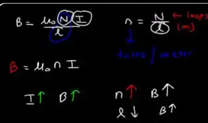
"B is equal to mu0 times N times I divided by L. Lowercase n is equal to capital N over L. Capital N represents the number of turns or loops, L is the length in meters. So lowercase n is the number of loops or turns per meter."
"As the current increases, the strength of the magnetic field will increase. The second way to increase the magnetic field is to increase the number of turns. ... If you can decrease the length, the magnetic field will increase as well."
A solenoid — a tightly-wound coil of wire — has a remarkable property: the magnetic field inside is nearly uniform everywhere except near the ends. It's the same magnitude at the center, at the edges, near the wall, or along the axis. This makes solenoids incredibly useful as "magnetic bottles" for generating controlled fields.
Why it's uniform: each loop of wire contributes its own B field; when you stack many loops closely, the fields from all the loops reinforce along the axis and cancel perpendicular to it. The inside of the solenoid "sees" contributions from loops on both sides, which adds up to a constant vector.
Outside the solenoid: the field is nearly zero. All the flux from the inside comes out one end and loops around to the other end. If you could see field lines, they'd look like those of a bar magnet, with N and S poles at the two ends. In fact, solenoids and bar magnets are magnetically indistinguishable from the outside — Ampère's original insight that magnetism comes from current loops.
Three ways to make B stronger:
- Increase I — more amps → more field (but the wire heats up as I²R)
- Increase n (turns per meter) — pack more windings into the same length
- Decrease L while keeping N — same number of loops compressed tighter
The "n = N/L" relationship: what matters physically is density of turns, not total turns. A 100-turn coil that's 1 cm long has the same field strength as a 10,000-turn coil that's 1 meter long (both have n = 10,000 turns/m). Every real solenoid formula depends on n, not N.
Example 8 — 15 cm solenoid, 800 turns, 5 A
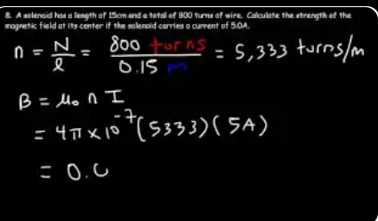
"A solenoid has a length of 15 cm and a total of 800 turns of wire. Calculate the strength of the magnetic field at its center if the solenoid carries a current of 5 amps."
"800 divided by 0.15 — that's equal to 5,333 turns per meter. ... The strength of the magnetic field at the center, it's about 0.0335 Tesla."
Solenoid problems are usually the easiest on an exam because the formula B = μ₀nI has only three inputs: n (turns per meter), I (current), and μ₀ (the constant). There's no angle, no cross-product, no integration. Just multiply.
The one trap: "n" is turns per meter, not total turns. If you're given N = 800 turns and length L = 15 cm, you must divide: n = N/L = 800/0.15 ≈ 5,333 turns/m. Forgetting this conversion is the #1 mistake — students plug in 800 instead of 5333 and get a field 150× too small.
Always convert cm to m first: 15 cm = 0.15 m. If you use 15, you'll get B off by a factor of 100. SI units throughout, always.
Sanity check the answer: 0.0335 T ≈ 335 Gauss. Earth's field is about 0.5 Gauss, so this solenoid is 670× stronger than Earth's field — plausible for 800 turns at 5 A in a short cylinder. It's strong enough to visibly deflect a compass needle from many meters away, but nowhere near MRI strength (~1–3 T).
How to make a stronger solenoid: three knobs — more current (more heat), more turns per meter (tighter winding), or add an iron core (multiplies B by the iron's permeability μ, typically 100–5000× stronger). Real electromagnets combine all three. A typical electromagnet in a junkyard crane uses iron-core solenoids to generate ~1 T and lift cars.
Torque on a current-carrying loop in B
"What's going to happen if we have a current carrying loop inside a magnetic field? ... In a magnetic field, the loop is going to rotate — it's going to produce a torque."
"Place your thumb going up and your four fingers in a direction of the magnetic field. ... Notice that the palm of your hand opens into the page, and so that's where the force is going to be. ... On the right side of the loop the current is reversed, so it must be out of the page."
A rectangular loop has two sides where current flows up and two sides where current flows the opposite way. When you put this loop in a uniform magnetic field, each side experiences a force F = IL×B — but because the currents go in opposite directions, the forces are also opposite.
The geometry: current up on the right side + B pointing east → F into the page (by RHR). Current down on the left side + B pointing east → F out of the page. These two forces are equal in magnitude but opposite in direction, so the net force on the loop is zero. But they're applied at different points, so they create a couple — a pair of equal-and-opposite forces offset in space that produces pure rotation with no translation.
Why this is called a "couple": in mechanics, two equal forces acting in opposite directions along different lines of action produce only torque, never translation. It's the purest form of rotational force. Every current loop in a uniform field feels a couple — the loop spins in place but doesn't drift.
What the loop does with that torque: it rotates toward an orientation where its magnetic moment M aligns with B. Once aligned, the forces switch geometry: now both forces act along the same line (and in opposite directions), so the couple's moment arm collapses to zero and the torque vanishes. That's the equilibrium position.
Galvanometer connection: this is how old analog meters work. A small coil with a pointer glued on is placed between permanent magnets. Current through the coil produces torque, the coil rotates against a restoring spring, and the pointer's angle indicates the current's magnitude. Simple, elegant, and entirely based on τ = NIAB sin θ.
Top view — deriving τ = τ₁ + τ₂
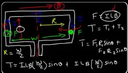
"F is equal to ILB sin theta. But the force is perpendicular both to the current and magnetic field, so sin 90 is one. So the force acting on the right side and on the left side of the loop is going to be ILB. ... There's no force on the top section and the bottom section of the loop. The reason for that is because the current is parallel to the magnetic field."
"Torque is the product of the force times the lever arm. So it's f times r. And if the force is at an angle, it's going to be f r sin theta. ... The axis of rotation is here ... so R is half of W, so r is W/2."
Torque is the rotational version of force. Just as force makes things accelerate linearly (F = ma), torque makes things rotate (τ = Iα, with I being rotational inertia here — different I than current). The formula τ = F·r·sin θ says torque depends on three things: how hard you push, how far out you push from the pivot, and what angle you push at.
Why r = W/2 (not W): the rotation axis passes through the middle of the loop, splitting the width W in half. Each long side of the loop is therefore only W/2 away from the axis. This is the "lever arm" for each of the two forces.
Why the top and bottom sides produce NO force: if the loop is oriented so the long sides (length L) are perpendicular to B, then the short sides (length W) must be parallel to B. The force F = ILB sin 90° = ILB only works when current is perpendicular to B. When parallel, sin 0° = 0, so force = 0. The top and bottom wires just sit there doing nothing.
Both forces push in the same rotational direction: the left wire's force pushes it "out of the page," the right wire's pushes it "into the page" — but both produce torque in the same rotational sense about the center axis. So the torques add (τ_total = τ₁ + τ₂), not cancel.
Why this matters: this is the fundamental operating principle of every electric motor. Current flowing through a loop in a magnetic field produces torque; the loop spins; by continuously switching current direction with a commutator, you can keep the torque always pushing in the same rotational sense forever. From a 3-gram drone motor to a 3-ton electric train motor, they all use exactly this geometry.
τ = N I A B sin θ · M = N I A
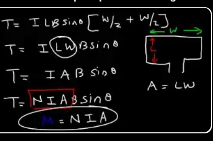
"Half plus half is a whole, so T is equal to I L W B sin theta. ... For the rectangular loop ... the area of the loop is basically the length times the width. So A is L times W. So let's replace LW with A."
"If you have two loops, the torque is going to be twice as strong. Three loops, three times as strong. So we need to add N to this equation for the number of loops. So it's N I A B sin theta. ... The quantity NIA is known as the magnetic dipole moment, represented by capital M."
The quantity M = NIA is called the magnetic dipole moment of the coil. It's a single number that summarizes "how magnetic" a current loop is — combining all three things that matter: how many turns (N), how much current (I), and how big the loop is (A).
Why bundle them together? The torque formula τ = MB sin θ looks simpler and cleaner with M in place. It also makes the analogy to electric dipoles clearer: τ_elec = pE sin θ (for electric dipole moment p in field E), τ_mag = MB sin θ. Same form, different "dipole strength."
Units of M: amps × meters² = A·m². A bar magnet the size of your thumb has a magnetic moment of around 0.1 A·m². A neodymium fridge magnet has about 1 A·m². The Earth, as a giant magnetic dipole, has M ≈ 8 × 10²² A·m².
Scaling with N: doubling the turns doubles the torque because each loop independently contributes NIA·B·sin θ, and they add in phase. This is why electromagnets use thousands of tightly-wound turns — it linearly multiplies the force without increasing the current (and therefore without overheating the wire).
Why the width W cancels into A: in the derivation, you see (w/2 + w/2) = w appear when adding the two torques from the two wire segments. Then LW = A, and the formula collapses to τ = IAB sin θ per turn. What looks like a rectangle-specific derivation actually works for any loop shape — the only thing that matters is the enclosed area A.
Defining θ via the loop's normal vector A⊥
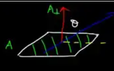
Caution: θ in the torque formula is the angle between B and the loop's normal, not between B and the loop's face.
"Let's draw the normal line perpendicular to the face of the loop. ... The red line is the normal line that's perpendicular to A. And sometimes the magnetic field is not going to be parallel or perpendicular to the surface — it can be [at] an angle."
"The angle theta is between the magnetic field and the normal line, which is perpendicular to the surface of the coil. ... So theta is between B and the normal line."
The single biggest source of errors in magnetism problems is: the angle θ is measured from the normal to the loop's face, not from the face itself. Students constantly mis-identify this angle and get signs and magnitudes wrong.
What's a "normal vector"? Imagine an arrow sticking straight out of the loop's flat surface, perpendicular to it, like a flagpole on a round table. That arrow is the normal vector (written A⊥ or n̂). If the loop is lying flat on the ground, its normal points straight up. If the loop is vertical, its normal points horizontally out of the face.
The conversion rule: if a problem tells you "B is parallel to the loop's face," that's 90° from the normal (→ max torque, sin 90° = 1). If it says "B is perpendicular to the loop's face" (= passes through it), that's 0° from the normal (→ zero torque, sin 0° = 0). Always convert "angle from face" to "angle from normal" by subtracting from 90°.
Why physics uses the normal and not the face: because the flux formula Φ = BA cos θ uses the same convention. Every formula involving a "loop's orientation in a field" — flux, induced EMF, torque, magnetic moment — is defined relative to the normal. This keeps all the equations consistent.
Quick gut check: if you set up a problem and the answer doesn't match the expected behavior (e.g., you expect maximum torque but get zero), check whether you used the correct angle. Swapping "angle from face" with "angle from normal" flips your sin to cos and your max to zero.
Three torque cases — θ = 90°, intermediate, 0°
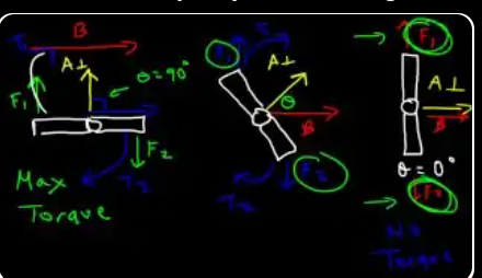
"Let's say the magnetic field is at an angle of 90 degrees. When it's at an angle of 90 degrees, you're going to get the maximum torque possible."
"Let's see what happens when the angle is zero. ... In this case, the normal line is parallel to the magnetic field, so therefore the angle between the two is zero, and when this happens, the magnetic field is perpendicular to the face of the coil. ... There's going to be no torque."
"If you look at the two forces F1 and F2, notice that they're parallel to the lever arm. Anytime you have a force that's parallel to the lever arm, it cannot create a torque. ... Let's say this is the top view of a door. Here's the lever arm R. The only way for you to push a door is to apply force perpendicular to the lever arm and the door is going to turn. If you try to push a door from this side, it's not going to move — it won't turn. And that's what's happening here. The axis of rotation is here, and the way the forces are oriented — since they're parallel to the lever arm, which is R — there's going to be no torque, there's no rotation."
"The maximum torque occurs whenever the angle is 90 — that is, the angle between the magnetic field and the normal line. So whenever the magnetic field is parallel to the face of the coil, you're going to have maximum torque. Whenever it's parallel to the face of the coil, it's perpendicular to the normal line — the angle is 90. And whenever the magnetic field passes through the coil, that is, when it's parallel to the normal line, there's going to be no torque — the angle is zero."
"If we look at the first picture on the left, F1 will create a torque that will cause it to rotate in the clockwise direction, and F2 will also create a torque that will cause the system to rotate in the clockwise direction. Once it rotates, it's going to move towards picture two. ... Eventually the system is going to reach this point ... but in the third diagram the net torque is zero. ... The net torque and the net force is zero for the third diagram, which means it's at equilibrium. So basically the loop moves from this position from an angle of 90, and the magnetic field causes it to rotate to an angle of zero, and then it stops."
A current loop in a magnetic field is not in equilibrium at θ = 90° — it's at the position of maximum twist. The loop "wants" to rotate toward θ = 0°, where its normal vector lines up with B. This is exactly analogous to a compass needle, which always twists until it aligns with Earth's magnetic field.
Door handle analogy: imagine pushing a door. If you push perpendicular to the door (from the face), it swings open — maximum torque. If you push parallel to the door (along the edge), nothing happens — zero torque. The force has to have a component perpendicular to the lever arm to produce rotation. For the current loop, the lever arm is the width of the loop, and F = ILB is the force on each side.
Stable vs. unstable equilibrium: at θ = 0° (normal aligned with B), the loop is at stable equilibrium — any small rotation creates a restoring torque that pushes it back. At θ = 180° (normal anti-aligned with B), the loop is also in equilibrium, but unstable — any tiny rotation sends it flipping around to θ = 0°. This is why bar magnets flip when you put them near each other: they seek the stable N-to-S alignment.
Energy story: the potential energy of a magnetic dipole in a field is U = −M·B cos θ. At θ = 0°, U is minimum (most negative) — that's the stable position. At θ = 180°, U is maximum — unstable. At θ = 90°, U = 0 — but the torque is maximum, so the loop starts swinging immediately.
Why compasses work: the compass needle is a tiny magnetic dipole. Earth's B field applies torque until the needle aligns with it (north pole of needle pointing toward magnetic north). Same physics as this slide, just scaled down to a pocket navigation tool.
Example 9 — circular coil, R = 30 cm, 50 loops, 8 A, 5 T
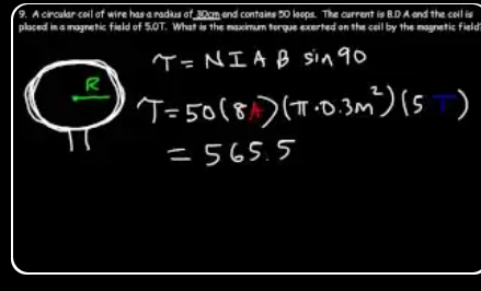
"A circular coil of wire has a radius of 30 cm and contains 50 loops. The current is 8 amps and the coil is placed in a magnetic field of 5 Tesla. What is the maximum torque exerted on [the] coil by the magnetic field?"
"To calculate the torque, it's equal to N I A B sin theta. Now if we wish to find a maximum torque, then the angle is going to be 90, and sin 90 is equal to 1. ... You should get 565.5 [N·m]. ... The unit for torque is newtons times meters."
When you see "R = 30 cm" for a circular coil, the key move is computing A = πR² = π(0.3)² ≈ 0.283 m². Notice how the 30 cm must become 0.30 m before squaring — if you forget the conversion, you'll be off by a factor of 10⁴.
Why R² (not R)? Torque depends on area because the magnetic moment M = NIA counts how much "magnetic dipole strength" the loop carries. A bigger loop encloses more flux for the same current, so it interacts more strongly with the external field. Since A = πR² for a circle, doubling the radius quadruples the torque.
The order of plugging in: (N)(I)(A)(B) = (50)(8)(0.283)(5). A smart way: group (NI) = 400 first, then (NIB) = 2000, then multiply by 0.283 to get 565.5. Or any order that gives you clean intermediate products.
565.5 N·m is a LOT of torque. To put it in perspective, a typical car engine produces ~300 N·m of peak torque. So a 30-cm coil carrying 8 A in a 5 T field twists with roughly twice the torque of an engine. This is why industrial motors use coils in strong fields — you can generate huge mechanical forces from compact wire geometries.
Connecting to later: this is also exactly how electric motors work. A spinning coil in a field experiences torque — that's the fundamental mechanism. The tricky part is using a commutator to keep the torque always in the same rotational direction as the coil turns; otherwise it would oscillate and never complete a rotation.
Example 10 — rectangular coil, find B for 1200 N·m
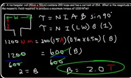
"A rectangular coil contains 200 loops and has a current of 15 amps. What is the magnitude of the magnetic field required to produce a maximum torque of 1200 newton times meters?"
"Since we're using the maximum torque, the maximum torque occurs at an angle of 90 degrees, so this is going to be sin 90. ... Let's multiply 200 times 15 times 0.4 times 0.5 — so that's equal to 600. ... 1200 over 600 ... is 12 divided by 6, and that's 2. So the magnetic field is 2 Tesla."
This problem is a "find the unknown variable" twist on the torque formula. You're given the torque and asked to find B — the opposite of most problems where you're given B and asked to find τ. The trick is just algebra: rearrange τ = NIAB sin θ to solve for whatever's missing.
Why max torque means sin θ = 1: the problem specifies maximum torque, which pins the angle at 90° because sin 90° = 1 (the biggest possible value). That simplifies the equation to τ = NIAB, and now you can directly solve: B = τ / (NIA).
Order of operations matters: compute NIA first (200 × 15 × 0.2 = 600), then divide τ by that number. This is much cleaner than trying to plug everything in at once. In general, when you have a formula with many factors, evaluate constants first.
Units sanity check: [τ] = N·m, [N] = dimensionless, [I] = A, [A] = m², so [NIA] = A·m². Then [τ/(NIA)] = (N·m)/(A·m²) = N/(A·m) = T. Units work out to Tesla. Always verify units on derived answers.
Real-world context: 2 T is a strong field — about the strength of an MRI machine. For perspective, Earth's magnetic field is ~50 μT (40,000× weaker), and a typical fridge magnet is around 5 mT. Electric motors in hybrid cars use fields around 1–2 T in their rotor windings, producing torques that launch the vehicle.